LED Matrix display
|
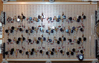
This display programmer needs eight bytes of ram each ram board has two
bytes so you will need to make four of these boards each bit is made up of four transistors two to hold the 0 or 1 one to enable the bit for writing and one to enable reading of the bit all of the read enable transistors for the byte are connected so that when the read enable line is pulled high it outputs the whole byte. |
|
| ram.pdf |
|
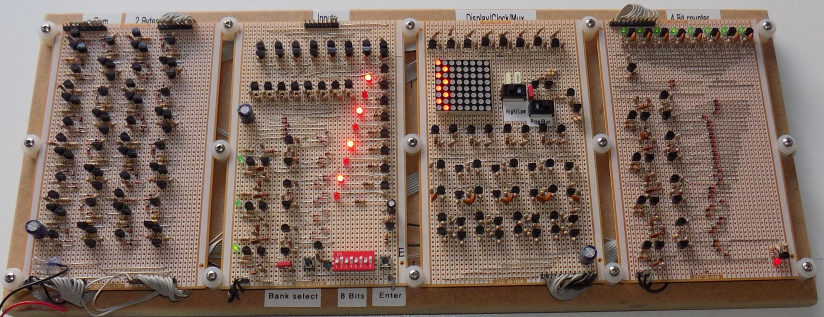
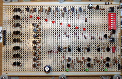
This board has a three bit binary counter to select the ram bank data line
you advance through the banks by pressing the bank select button to set the eight bits in the selected byte of ram you use the dip switches to set the bit to 0 or 1 when you have set the dip switches you press the enter button and the data is stored in the selected bank of ram. |
|
| inputs_board.pdf |
|
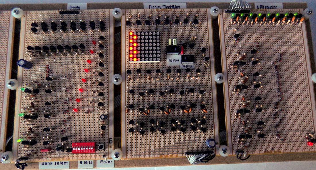
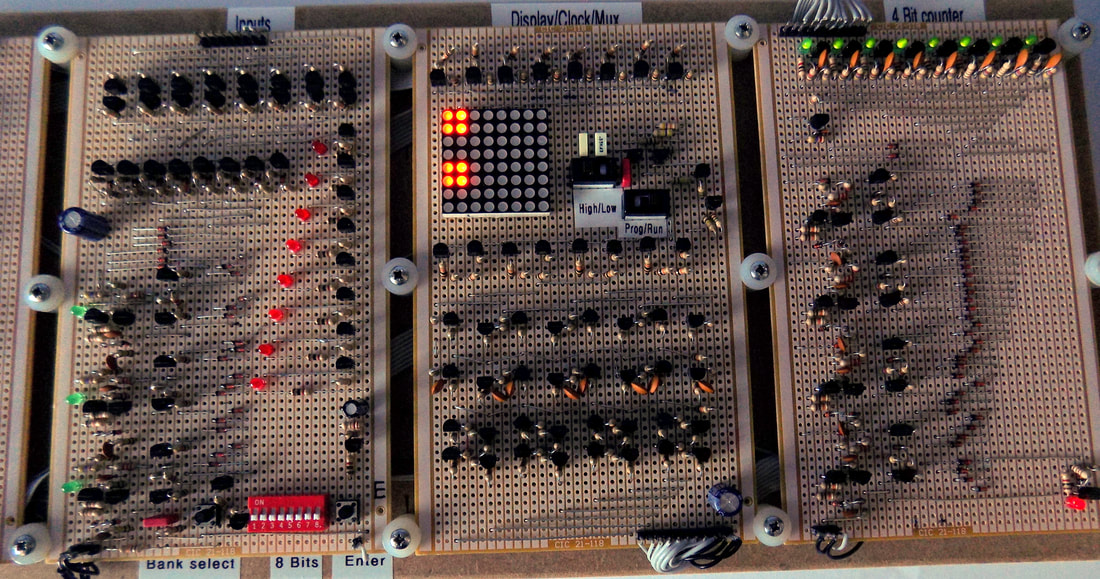
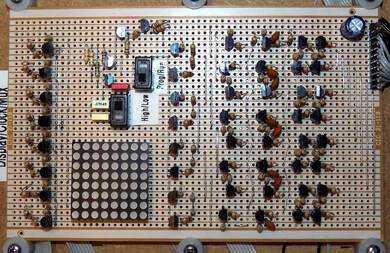
This board has an 8 x 8 common anode led matrix and a clock
the clock has two speeds high about 500Hz and low about 8Hz when programming you can set the clock to low speed and you can see the counter board step through the bits as they are stored it also works in high speed mode but it is to fast to see there is also a switch to switch between programming and running the display the mux selects the write enable lines and the read enable lines. |
|
| display_clock_mux.pdf |
|
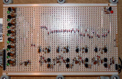
This is a four bit binary counter that use diode logic to convert the binary
number to a single output this counter runs the display and ram storage the counter speed is controlled from the clock on the display board |
|
| 4_bit_counter.pdf |