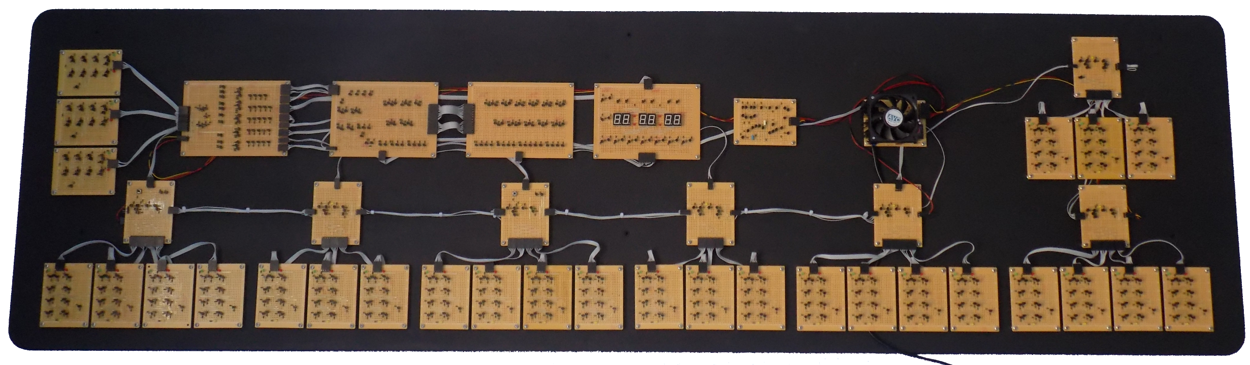
Number of parts
Transistors 777, Resistors 1223, Leds 136, Crimp Connectors 455, Boards 41, Solder 500grams
Flip Flops
|
The clock requires 28 of these boards it has three for the display multiplexer seven for the divider to divide the 50Hz down to 1Hz four to count the seconds units three to count the seconds tens four to count the minutes units three to count the minutes tens
and four to count the hours. The yellow led is to show you the clock signal traveling through the boards the green led on the output represents a zero and the red led represents a one.
|
    | ||
Display Multiplexer
|
The multiplexer selects each of the five digits and sends the correct set of bits to the seven segment decoder to display the number it also send a signal to the decoder board to set it to either decode zero to nine or to decode 1 to twelve the clock for the multiplexer comes from a 555 timer made from single transistors the frequency is about 300Hz the multiplexer counts up to six so it displays the five digits and then blanks the display for one count.
|
    | ||
Seven segment decoder
|
The seven segment decoder is split over two boards to make it easier to visualise the bits flowing down through the gates and out of the headers at the bottom of the boards the left-hand board also has the circuitry to detect if zero to nine should be displayed or one to twelve.
|
        | ||
Seven segment display
|
The seven segment display board uses common cathode seven segment displays only one of the segment is on at a time except
on the hours where if selected by the decoder the one will be on with the units
|
    | ||
555 Timer
|
The 555 Timer circuit is used to provide the clock signal for the multiplexer the frequency is about 300Hz
|
   | ||
The resets
|
The flip flops plug into the reset boards at the bottom the clock signal come in on the right hand side and then goes through the flip flops when the reset board detects that the set number has been reached it pull the flip flops reset pin low when the reset board detects the boards have reset it sets the reset pin high at the same time it sends a pulse to the next reset board on the left hand side
the bits counted by the flip flops go to the multiplexer through the header at the top of the board the time can be set with the button on the minutes units and hours reset boards when you press the button it disconnects the main clock and send a 2Hz clock signal into the reset board.
|
               | ||||
The power supply
|
The clock runs on five volts and the current draw is about 700mA most of this is to power the leds there are ninety four leds and six seven segment displays the power supply needs a AC voltage source of eight to twenty volts the power supply then rectifies this to DC through a bridge rectifier and then regulates this down to five volts the regulator is made of zener diodes transistors and resistors it has over current and over voltage protection it also taps off the fifty Hz from the input side of the bridge rectifier and uses a Schmitt trigger to turn it into a square wave output.
|
     | ||
